3D Systems has just announced a new 3D drawing application at just $49. It's called Cubify invent.
Cubify Invent Product Introduction Image
I haven't had an opportunity to work with it in any real depth. But, from the little time that I have spent with it, Invent looks like a relatively easy and very capable 3D drawing package.
While it steers clear of technical jargon, like "BOOLEAN", it has a full compliment of boolean functions. And, for me, that is one of the most critical capabilities for a truly useful 3D printing application.
You can download a 15 day trial from the product's page.
My initial feeling is that Invent is going to be a bit more time consuming when creating the same objects than Moment of Inspiration. However, there is a substantial cost differential and Invent is designed to be "Print Ready" and that could be a big equalizer.
I am NOT going to post a review immediately. I'm far too familiar and comfortable with my current 3D application to be able to be fair to Invent until I have had some time to get comfortable with it as well. I don't want to confuse differences in style with differences in capability.
But, I will post an introduction to the product from the point of view of how to get started.
Fortunately, Cubify has included a number of Getting Started Videos. And that is where I will be beginning my own quest to understand and use it effectively.
One of the things that I can point out is that the process of creating a 3D object begins with a 2D sketch. That immediately gives it a familiar feel. In fact, to create the simplest 3D objects, all one has to do is to extrude that sketch. So, it certainly shows promise as an entry level consumer 3D tool. But, that would not be enough if that were all there is. Fortunately, it is not. It appears to be reasonably comprehensive and the videos are an excellent introduction.
Only those that have had to deal with the mess of reels of filament can fully appreciate the luxury of having a cartridge fed 3D printer.
It is the cartridge, more than any other feature, that makes the Cube suitable for living areas in homes and public areas in offices. It take 3D printing from the world of the hobbyist and opens it up to the world of businesses and average consumers.
One of the first things that I did with another consumer product that I admire, the Keurig coffeemaker, was to buy a carousel to organize and present the coffee pods to guests. I even travel with a Keurig Mini Plus and a bamboo coffee pod drawer system. It definitely adds convenience and value to owning a Keurig.
It immediately struck me that, like Keurig K-Cups, the Cube cartridges could be easily and conveniently organized with a simple rack. So, I've designed one that can be printed with the Cube.
Cube Cartridge Rack & Filament Clip System
The Cube Cartridge Rack system is designed to hold 3 Cube cartridges and includes 3 clips to hold the ends of the filament neatly and safely. It includes a slot to accommodate the retaining screw. It makes swapping filament colors a snap.
Here is a video that show the rack holding 3 cartridges...
It's nice being able to augment and improve our Cube experience with items that we can either design or download and print ourselves. This one is particularly useful. Like all my designs, theSTL for the Cube Cartridge Rack w/clips can be downloaded from the Cubify.com store for the minimum cost permitted.
I do have to warn you that it is a 12 hour print job! So, don't start it if storms are in the areas. It would be REALLY annoying to get 10 hours into the job and have the electric go out! (Can you hear experience talking?)
In response to a previous blog entry, someone asked me to see if the dimensions of a blind hole are similar or the same to a standard hole. A blind hole is simply a hole that does not go all the way through an object.
I'm here to please... and, the results are in.
Test Method
I created 3 objects with an outside diameter of 40mm and an inside diameter of 20mm. One of the objects was exactly like the "washer" in the previous test. It was 3mm tall. The other two objects were 20mm tall. One had a hole completely through the object and the other had a blind hole that went into the object about 15mm.
Here are the measurements...
3MM Washer - Hole
3mm Tall Cylinder: Hole - 18.41mm Inside Diameter
The 3mm tall washer had an inside diameter, in this test. of 18.41mm.
The second 20mm tall cylinder, with the blind hole, had an inside diameter of 18.38mm.
Observations
The strangest result of this test was that the 3mm washer, which one would expect would have the exact same dimensions of the first test, had an inside diameter that was more than .7mm more than the first test. In test #1, the inside diameter was 17.71 and in this test it was 18.41!
Otherwise, the differences don't seem all that remarkable. The distribution from smallest to largest is mildly interesting. The greatest degree of difference is between the two objects with holes. The blind hold object turns out to be the SMALLEST! Is this due to the greater mass of the blind hole object, which results in more overall shrinkage? I don't know. But, I do find the differences to be intriguing.
Getting to know our Cube printer (or any 3D printer) is very important. Discovering how it behaves in various situations will help us become more productive with less need for multiple re-design & print iterations, which saves filament.
One of the most important things we can know is the relationship between the dimensions of printed posts vs. the dimensions of printed holes. Matching posts and holes allows up to make parts of different colors by printing two parts of different colors that snap together using a post on one part that goes into a hole in the other.
Fortunately, this relationship is easy to test. I've created a sample set of objects that will be available as an STL on the Cubify.Com store. As usual for my designs, it will be sold at the lowest permissible cost.
Posts and Holes Test STL
Each hole includes raised lettering indicating the designed size. Each post has a small handle that doubles as a size label. The holes and posts range from 3mm to 22mm. Both post and hole has been chamfered for easier fit. Below is the finished print still on the Cube printing bed.
Printed Post and Hole Test Objects
Theoretically, each post should fit into its corresponding hole, as indicated in this image.
Post & Hole Design Match
But, due to the nature of extrusion printing, that is not what we see. We find that we will have to make adjustments in order to make things fit by making holes with designed dimensions that are larger than the post meant to go into them. Here is the actual match in the case of my print.
Posts in Actual Matching Holes
Notice that the largest post, 22mm, cannot be fitted into any hole. And, interestingly, posts 12mm to 20mm fit nicely into the holes that are 2mm larger in diameter. The 20mm post fits into a 22mm hole. That's nice and neat and probably holds true as posts and holes get larger.
It's a bit messier in the 3mm to 11mm range. Because we increased each hole by a full 1mm, there are posts that do not neatly fit into any of the holes. The 3mm post, for instance is too big for the 5mm hole; but, too small for the 6mm hole. The same kind of things is true for the 4mm, 10mm and 11mm posts. To really get a reasonably good match we would have had to increment the holes by .5mm.
Here is the mapping overlaid on the original design.
Diagram Matching Posts and Holes
The fact that we have to design matching posts and holes in different sizes is not a big deal once we learn that this is what we have to do. Having a tool like the above helps us be accurate the first time when we design. It's well worth the material costs to create it because it will save a LOT of material later.
All extrusion 3D printers lay down a strand of molten plastic. These strands are combined to build the 3D object. The width of a strand is dependent on the width of the opening in the extrusion Hot End tip and the speed of both the extrusion and the travel of the hot end tip.
While I have no idea what algorithms are used in determining the center of the tip during printing, we can create test objects that give us some idea as to how the print engine interprets our designs. We do this by creating specially designed objects of known size and shape. We can then print these objects and measure them to see how they compare to our original drawings.
I believe that the PrintJet opening in the cube is .5mm. This means that plastic should extrude at a minimum of .5mm, with .25mm on each side of the center of the PrintJet. However, the Cube prints in .25mm layers. This means that the plastic is flattened by the PrintJet tip. Push down on the top of the molten plastic and you should get a strand that becomes WIDER than .5mm. Pushing down creates a strong bond between layers. But, it also means that there may be some difference between the object as we design it and as it printed.
We're going to try to identify those differences with a test file. This video demonstrates how the test file was created using Moment of Inspiration (www.moi3D.com).
Most people with experience with 3D printing would say that beginning with .25mm wide objects is pointless since the PrintJet head, itself, is .5mm wide. But, what we are looking for is the BEHAVIOR of the printer from very narrow to wider. We're asking the question, "At what point does the printer start to best match the designed width of the object. So, beginning low and going up makes some sense to make sure we cross that sweet spot.
Once the file was created, I printed it on both the Cube 3D printer and the RapMan 3.2 3D printer. This provides some context and comparison that is helpful in trying to understand how to design for 3D printers.
We start with the Cube printer result...
Object 1: A Cube .25mm Wide and 3mm High
Designed .25mm - Printed .83mm
One of the things you notice when print this test is that ALL of the cubes were printed in two passes, no matter how narrowly they were designed. The printer tries to create a perimeter for the object. And, in this case the perimeter lines actually must have overlapped. Otherwise, the minimum with would have been 1mm. .83mm, it would appear, is the minimum width for an object.
Object 02: A Cube .5mm Wide and 3mm High
Designed .5mm - Printed 1.05mm
It's interesting that when we moved to .5 mm in our design the printer still created a perimeter. But, it did not overlap the extrusion, It laid both the directions side by side almost perfectly to create an object just over 1mm wide. The object looks well fused.
Object 03: A Cube .75mm Wide and 3mm High
Designed .75mm - Printed 1.04mm
As we move to an object that was designed to be .75mm wide an interesting artifact begins to show itself. Notice that the walls have a gap! This is a very well known, if somewhat puzzling, artifact within the 3D printing community. At first, it's very annoying. But, you soon learn to design to minimize its affect. In this case, the object printed at 1.04mm
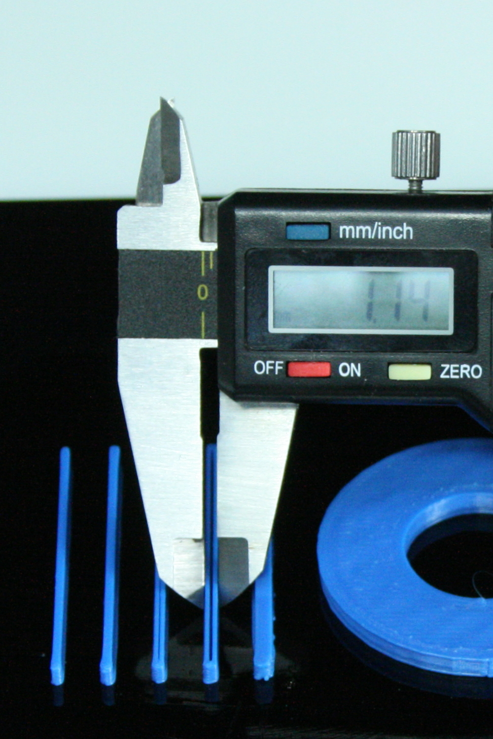
Object 04: A Cube 1mm Wide and 3mm High
Designed 1mm - Printed 1.14mm
One would think that if the Printjet is .5mm then anything above that width would be sized correctly. Logic suggests that a 1mm object would be right on the money. But, remember, the molten plastic is being pressed down and widened out. Obviously, the printer thinks that's enough to fill the gap between the walls. But, no so! The gap is even wider! But, oddly enough, the delta between our designed width and the actual width has started to narrow to just .14mm. That's pretty close, even if it is a bit ugly.
Object 05: A Cube 1.25mm Wide and 3mm High
Designed 1.25mm - Printed 1.50mm
At a design specification of 1.25mm the delta between the design and the actual print broadens from .14 to .25. But, the object resumes its solid look. There is no gap between the walls.
Object 06: A Cube 1.5mm Wide and 3mm High
Designed 1.5mm - Printed 1.54mm
At a designed width of 1.5mm, things start to look up for accuracy. The Cube printed the object at 1.54mm... a delta of just .04mm and that is wonderful. It would appear that this may be the sweet spot for both design accuracy and solidity.
Object 07: A Cube 1.75mm Wide and 3mm High
Designed 1.75mm - Printed 1.66mm
Once again we see the gap show up between the walls. And, at 1.65mm, for the first time, the printed object is NARROWER than the design specifications.
Object 08: A Cube 2mm Wide and 3mm High
Designed 2mm - Printed 1.96mm
The trend of being more narrow than the design specifications continues with an object with 2mm walls. And, so does the artifact that leaves a gap between the walls. The printed object is 1.96mm, which is pretty accurate. But, that gap sure does bother me.
Object 09: A Cube 2.25mm Wide and 3mm High
Designed 2.25mm - Printed 2.41mm
Why the objects reverse the trend and be bigger than designed is a mystery. But, that is exactly what happened in this test when we move to a wall thickness of 2.25mm! It printed solidly. And, that is a good thing. But, it also printed at 2.41mm. So, we have to be aware of that when we design.
Object 10: A Cube 2.5mm Wide and 3mm High
Designed 2.5 - Printed 2.78mm
The last of the extruded rectangles was designed at 2.5mm. It printed at 2.78mm. That's not perfect; but, it's not all that bad either. Again, we just have to remember that not one of our measurements so far is printing exactly as designed.
Circle Inner Diameter - 20mm
Measuring inner Diameter
Inner Edge: Designed 20mm Diameter - Printed 17.71mm
I used the inner measurement blades of the digital caliper to measure the inside edge of the circle. It was designed to be 20mm. It printed at 17.71. This is just about what I expected based on previous experience. If the tip of the extrusion PrintJet is centered right on the circumference of a 20mm circle then you need to account for the .25mm+ on each side of that center line. Taking into account the extra width due to compressing the layer and it comes out pretty close to our expectations and calculations. But, we always have to keep the fact that inside diameters will be SMALLER than designed in our minds when we design.
Circle Inner Diameter - 40mm
Outer Edge: Design 49mm Diamter - Printed 39.17mm
I could not believe my eyes when I measured the outside diameter of the circle object. In fact, I checked and re-checked the results! I fully expected the outer edge of the ring object to be LARGER than designed. And, for the same reasons that the inner diameter was SMALLER... the spread from the center of the Printjet tip. But, it was not. Apparently, the software does some compensating with it comes to outside edges of circles! It's still not 40mm. But, it's pretty close for the total size.
WHAT IT ALL MEANS...
For most of us it simply means that we need to keep these behaviours in mind when designing objects to be printed on the Cube or any other extrusion style 3D printer.While the numbers were a bit different, Axon2 for the RapMan, produced very similar results.And, from posts in forums it seems to be a universal 3D extrusion type printer behavior.
The only people seriously affected by this behavior are those that want to use a single design on both an extrusion 3D printer and a high end 3D printer. That doesn't bother me a lot because my software package is so versatile and quick to use that creating two working designs is not all that difficult.
It's just something we all have to keep in the back of our minds as we design. And, I will have some test designs that will help nail down the most common parts interfacing sizes. Remember, plugs will generally be bigger and holes with generally be smaller in most cases. So, you cannot expect that a plug that you have designed at 8mm will fit into a hole that you have designed at 8mm. Your probably going to have to make one or the other bigger or smaller as part of the design process. The key is to get to know your printer so making these allowances becomes second nature.
I hope this was helpful. The next installment will be a plugs vs. holes demonstration.
I have no idea what Celestial Circuits is going to officially call this part. So, for now, I'll simply call it a rocket pod. Here is an image of two iterations of the design.
Celestial Circuits Rocket Circuit Board Pod
The only difference is that the design on the right has rests for the ring so that it's even on both top and bottom. You can see a small piece of circuit board in the part on the left.
The legs that extend from the ring that holds the two halves together are segmented to allow for easier cutting or breaking to allow the rocketeer to custom fit the unit in any rocket. The item with be shown at a convention next week.
Any size is possible. Here is a version that takes a larger circuit board.
A Version to Accommodate Larger Boards
It was a fun project and I'm looking forward to seeing some test flights. The boards that will be carried in this pod do a number of things. Some capture telemetry data that can be played back via a video game-like simulator that recreates the flight on a computer for analysis.
A 3D printer can open the doors to some very, very interesting opportunities.
The blue is a nice color for this application, isn't it? Very cool.
Even cooler is that I finally now have all the colors to show to you.
There are more than one type of crazy people in the world. There is the true crazy that can usually be found in just about every family. And, then there are the "delightfully crazy" that are just plain WAY out there when it comes to life. These are the truly creative people.
Sooner or later you are going to come to understand that I not only like hanging around with those that fall into the delightfully crazy category... I LOVE to hang around with them. I cannot even begin to tell you how these friends have expanded my world in just about every direction!
One of these friends is Steve Bress of Celestial Circuits. And, he recently asked me to turn one of his space related designs into a functional object using the Cube printer.
I want to tell you about it. But, before doing so, I want to give you a little bit of background about Steve. I first met him back in the early 1980's when I needed to find a game programmer. Astrocade, the maker of the Bally Professional Arcade, for whom I'd worked, had been among the first casualties of the early round of video game console manufacturers. So, I'd designed some children's activities which had been picked up by a publisher and needed someone to program the various version.
In the mid-1980's I was the designer and he was the programmer for what we believe was the first professional desktop video application for the PC, which was marketed as the JVC Video Titler. This led to our designing and programming Pinnacle Systems first video product... a video effects generator.
Around that same time, another of those delightfully crazy friends of mine, John Perkins, asked me to join him on a project for Hasbro under Nolan Bushnell's company, Axlon. It was to be video game based on video tape. The game's code name was NEMO and while it never came to market, there is actually proof of its existence in this video. John Perkins found a way to embed multiple images into a single videotape. In the meantime, Steve Bress attacked the need for multiple sound tracks (Beyond two) in an entirely new and wildly creative way by combining and decoding quarter waves. Very cool stuff.
Moving on from there Steve became involved in the private space industry and, working with a company called Lunacorp and Carnegie Melon University, Their idea was to put a rover on the moon that people could control from earth from motion platform chairs in museums. Steven Bress designed the electronics and systems that communicated between the rover and the motion platform chair. To test the electronics, a warehouse was set up with a simulated moon surface and I would sometimes get to "pilot" the small remote control vehicle that represented the full sized rover. It was a blast. Every rock, hole, hill and valley was sent back to the chair for a fantastically fun experience. It's too bad that Lunacorp folded before the rover was parked on the moon.
Steve has continued to be involved in all kinds of space related activities. One of his latest projects involves building a system that can be used by students and others to capture real-time data from model rockets as they are fired. He needed a capsule that could be placed into the rocket and hold a small circuit board in place. He asked me to refine his original design and print out a few as samples.
I used Moment of Inspiration to create the design. It's fantastic for this kind of project because it is so precise and yet easy to use. Here is a screenshot of the final design that we ended up using.
Celestial Curcuits' Circuit Board Capsule
While it may not be all that clear in the above image, the capsule consists of 4 parts. The main capsule has two halves and the halves are held together by two rings that have extensions that can be clipped to fit the rocket body. It's fairly small and had to be printed to precisely fit a non-printed item, the circuit board.
Over the next few posts, I want to talk about are the design decisions that were made to optimize the part for printing on the Cube. And, as usual, a primary goal was no raft and no supports. I have to deliver the parts to Steve this evening. So, the next installment will have to wait a bit. I learned a great deal with this project and want to pass what I've learned onto you.
Here is the design as it will look put together.
Completed Part
I will give you one hint. Notice that the rings look larger than the circumference of the two halves. But, in actuality, they fit very tightly in the printed part. There is a reason for that. And, I want to discuss those reasons in deep detail.
In the meantime, try to find one or two delightfully crazy people with which to associate. One has no idea where it will lead when you open your life to delightfully crazy people!
If so, then this is the SECOND time you will here it.
Magic Glue comes with the Cube printer. It is a bottle of some mysterious substance that you spread on the bed of the Cube before you print. The bottle has a foam applicator that resembles that used with liquid shoe polish bottles.
The "Magic" that it performs is that it keeps the printed piece in place as the piece is printing and then allows you to releases the piece by dipping the bed into water after the print is done. It is water soluble proprietary glue. And, I love it.
It is what allows us to print many things without a raft.
It is what allows us not to break the piece taking it off the bed.
It is what allows us to not find a huge tangled wad of filament instead of a nicely printed object when we come back to check on the printer's progress. (Yes, I know this because sometimes in my hast I forget to use Magic Glue!)
I don't know who invented Magic Glue. It may be someone that I have met at 3D Systems or it may be someone at one of the far-flung subsidiaries that I will never meet.
But, I SO greatly admire that person, whoever they are... and I am VERY, VERY appreciative of their absolute brilliance!
One of the best things I like about my Cube printer is that it travels very, very well. It's light; yet, rugged in a way most previous 3D printers are not. It's a true party animal!
The object that you see below was printed in a hotel room after the head had been clogged due to my impatience and cleared using the technique described in an earlier article. Obviously, clogs are not fatal to the Cube as this video clearly demonstrates.
The Magenta filament that I had ordered arrived just before we traveled to Wilmington, DE. After a week without electric power it was great to be able to pick up the printer, put it in the car and take it with us to a place having power. And, of course, my granddaughters, who loved the green version of "Vase - Fire" wanted a magenta version!
Here it is...
Now, remember, this was printed entirely without supports or a raft.
I hope you are as impressed by that fact as I am.
But, I printed out another item on that trip that will prove its value for a long time to come.
THE DO NOT DISTURB HANGER LOCK.
We usually stay for multiple days when we travel. So, we are used to using the "Do Not Disturb" hanger. The only problem is that the hanger tends to fall off the door handle when the door is opened and closed. Not fatal. But, certainly annoying.
So, I decided to design and print a clip that would keep the hanger in place! This is owning a 3D printer at its finest. :)
Do Not Disturb Hanger Lock
It worked like a charm. It slipped over the door handle and slid back to lock the door hanger in place. It is this kind a ad-hoc capability that really makes a 3D printer pay for itself. It took less than four minutes to design using Moment of Inspiration and about 12 minutes to print.
As I have already said... the Cube travels well. Very well.
All of the glowing reviews I have posted about the Cube 3D printer are true, The quality of the prints has been remarkable. But, that does NOT mean that I have not been able to bring it to its knees.
And, by doing so, have made it less likely that you will end up doing so.
Remember when I ran out of filament? It happened when I was running it unattended. And, the reason it happened is that I failed to read the warning that came up on the LCD about not having enough material to complete the object as I was starting it.. I saw something; but, because I intended to photograph the piece for a stop-motion movie, I'd flooded it with lights. And, since I wasn't wearing my reading glasses, the brightness made it difficult to decipher.
I should have taken the time to go get my glasses. Therefore, the print never completed and the filament ran completely out.
I didn't think much of it and it took some time to obtain more filament. But, when I tried to load the new filament into the PrintJet I heard an all too familiar sound. In a 3D extrusion printer, if the extruder cannot move the filament forward, it makes a clicking sound. Virtually, all owners of 3D printers have heard it at some time or other. More often than not it means the print head is clogged. And, that was true for the clicking I was hearing from the Cube PrintJet.
I'm pretty fearless when it comes to tackling mechanical problems. So, I took off the Printjet cover to see if I could clear the clog. This drawing is my simple rendition of the extrusion system used in the Cube.
Cube Extrusion System
As you can see, there are three basic parts:
A top tube into which the filament is loaded
A gear and spring-loaded idler that pull the filament
A bottom tube which is heated to extrude the filament.
As you can plainly see, this is a brilliant design allowing for a nice small Printjet with direct contact with the filament. It allows them to put a motor, fan and extruder into a nice, compact Printjet package. The compactness of the design is wonderful; but, it does mean that it is difficult to reach material that has gone past the gear.
In fact, this is exactly what I found. The filament end had gone past the gear and was stuck in the bottom tube. There was just the slightest piece of filament in the gap between the lower tube and the gear. But, I could not get to it. I returned it to the factory and they replaced the Printjet.
The problem was that by ignoring the warnings on the LCD, I had allowed the filament to run out and go past the gears as it ran unattended. Had any part of the filament been sticking up from the Printjet, it could have been easily cleared.
The outcome of my experience was that 3D Systems redesigned the cartridge by attaching a small clip to the tail end of the filament so that if a user fails to heed the warning that there is not enough filament to complete a print job, the clip will keep the end of the filament from going past the gears, allowing the user to back the filament left inside the Printjet out. Sometimes manufacturers have to go out of their way to save us from ourselves!
If that were the ONLY way a user could clog the Printjet all would be well. But, I found out this weekend that it is not.
This past weekend, I was in Wilmington, DE for a few days visiting my granddaughters. Just before I left for the trip, part of my filament order came in and among the colors was magenta. I'd taken the Cube along for the ride and decided to make something for my granddaughters in magenta. This, of course, required removing the old cartridge to make way for the new.
Impatience was the problem. I made the mistake of trying to "help" the Cube back the old filament out of the PrintJet. I apparently pulled too hard causing some of the filament to remain in the bottom tube. Not good. I learned something new...
LET THE CUBE REVERSE THE FILAMENT WITHOUT HELP. ONLY PULL ON THE FILAMENT AFTER THE GEARS STOP TURNING.
Putting the new filament into the Cube, I heard that dreaded clicking sound. Once again, I'd clogged the head.
But, this time I wasn't 15 minutes from the factory and I wanted to make that magenta object for my granddaughters. So, I came up with a last ditch effort to solve my problem. Knowing there was a hobby shop near the hotel, I ran out and purchased the thinnest piano wire they carried. (Piano wire is commonly used in Remote Control airplanes.)
Before going any farther, I need to warn you that 3D Systems is NOT going to like what I did. The Print Head of the Cube is around 240C degrees and that is MORE than hot enough to cause serious burns. And, I am not telling you what I did so that you can do the same. I'm only relating my experience to say that I was able to get up and running again without having to send my Cube back to the factory.
As I mentioned earlier, I'm pretty fearless when it comes to tackling mechanical problems. So, using a piece of .piano wire with a diameter of 015" (.38mm), I was able to clear the clog and get on with the business of printing.
My method was to start the "Change Cartridge" process which heats the print head. The .38mm wire was small enough to insert into the hole at the bottom of the heated print head. As the filament in the bottom tube melted, I put slight back pressure on it until it moved back up the tube and out.
I didn't have tools to remove the cover of the Printjet. So, I don't know if the plastic was caught by the gear and pulled out or simply fell out of the bottom tube. Whatever the case, the outcome was that I was easily able to get up and running again.
The bottom line is that we need to be careful that we don't do something that causes filament material to be left in the bottom tube of the Cube. I have reported my latest experience to 3D Systems along with a suggestion that the nozzle of the Cube be redesigned so that it can be unscrewed by the user so that a clog could be removed from the top of the print head with simple tools.
Now, lest you think that the potential for clogging is limited to the Cube. Let me correct that notion with this link to a technical bulletin for an HP extrusion printer that costs over $15,000 US! And, there are numerous posts about Makerbot clogs. Just go to Google and enter "Makerbot Clog" to see just how many hits you find.
It happens. But, as the community of Cube users stumbles across actions that contribute to clogging, we can learn how to avoid those actions. And, that is what sites like this are all about.
Both instances I have had with clogging were caused by user error. Even so, 3D Systems immediately responded by coming up with a solution to make sure future users would not run into the problem when coming to the end of the filament.
In the case of the latter clog, I was up and running in little more time than it took me to drive to a hobby shop and back. This is an image of the piece that I printed for my granddaughters AFTER the clog was cleared.
I now have filament. And, was ready to do some more testing when the storm flew through our area and cut electrical supplies over a wide area.
I have taken the photos of the "fire" vase rotating and need to edit them into a movie format. But, I may not be able to post everything until early next week.


_0001.JPG)